Categories
- Aircraft, Helicopter, UAV, Spacecraft & related equipment
- Maintenance Repair Overhaul and Logistics Support
- Mechanical, Electro-mechanical, Hydraulic and Pneumatic components
- Metal Processing, Parts & Components
- Services (R&D, training, engineering, consultancy, …)
The beginning of the exciting story of LET, dates back in 1936 when a branch of AVIA Letnany was built in Kunovice to service AVIA planes. During the WWII the company was forced to repair the Junkers W34 and Arado Ar 96b for Luftwaffe and after the war it worked on almost all the types of aeroplanes that were flying in Czechoslovakia.
In 1957 the company begun to develop the famous L 200 Morava and four years later the Z 37 Bumble Bee, which both brought a huge commercial success. For a period of time LET also produced a light training aircraft L 29.
Over the years LET developed and produced a number of different gliders – Zlin Z 22, Z 124 Galanka, LF 109 Pioneer, Z 425 Sohaj. However the most popular gliders produced in LET are the famous Blaniks – L 13, L 23 and L 33.


Contact info #1
TRAINING
L410 TYPE RATING TRAINING COURSE FOR PILOTS
T-1-1 Ground school: 30 hours
T-1-1 CPT (cockpit procedure training): 6 hours
T-1-1 Simulator Training: 20 hours
A/C base training: 3,5 flight hours (8 landings)
A047: Indonesia
TRE check: 1,0 flight hour
DURATION: 12 days
ENTRY MINIMUM REQUIREMENTS:
- License ATPL or CPL ( IR )
- Required total flown hours for co-pilot 200h (100 as PIC )
- Frozen ATPL for co-pilot ( passed theory exams ATPL )
- MCC course or MPA plane flown before.
- Valid ME IR
- Valid Medical certificate
PLACE OF PERFORMANCE: Flight Training Centre located in Ostrava Czech Republic.
TYPE RATING COURSE FOR THE AIRCRAFT ENGINEERS
- Electro/avionics
- Airframe/power plant
- Universal (combination of electro/avionics & airframe/ power plant)
DURATION: 4 weeks (theoretical & practical part)
ENTRY MINIMUM REQUIREMENT: The training participants should be holders of valid ICAO/NAA/JAA/EASA aircraft license for turboprop aircraft of the same category as the L 410 aircraft, as minimum.
PLACE OF PERFORMANCE: Aircraft Industries, a.s. Training Centre approved as EASA PART-147 maintenance training organisation.
INTERNATIONAL AIRPORT
ICAO: LKKU, IATA: UHE
- ARP coordinates: 49 01 46 N 017 26 23 E
- Type of traffic permitted: IFR, VFR
- Category: non-public international airport
- Airport runways:
- 21C/ 03C 2000 x 30 m, concrete surface, load capacity PCN 33/ R/ B/ X/T
- 21L/ 03R 1690 x 60 m, grass surface, load capacity 25.000 kg
- 21R/ 03L 1480 x 80 m, grass surface, load capacity 25.000 kg
- Elevation: 581 feet/177 metres
- Reference temperature: 21°
- Instrument Approach Procedure: 2 NDB (GPS)
- TWR/Radar Frequency: 120.10 MHz
- Operation hours: Monday - Friday, from 08.00 to 16.00 LT, otherwise at request
AVIATION TRAINING COLLEGE
Aircraft Industries operates its own school for young mechanics. A comprehensive hands-on-four-year curriculum ends with a final exam plus an EASA recognized commercial licence for aircraft maintenance according to Part 66.
L410 UVP-E20 / L420
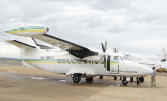
The L410 UVP-E20 / L420 aircraft, which is the latest and most advanced successor of the famous L 410 aircraft series, is a well proven 19 seat turboprop commuter aircraft with outstanding technical parameters and operational reliability, easy handling and simple maintenance.
The L410 / L420 aircraft have been in production for over thirty years with an impressive safety record. Owners and users from different regions of Europe, Asia, Africa and America appreciate the aircraft's remarkable ”hot and high” performance and excellent STOL capability. They especially value its tough and durable structure and the ability to operate under extreme climatic conditions ranging from –50oC up to +50oC. Its durable airframe and unique design offer exceptional performance both in the torrid desert heat of Africa and Latin America as well as the most frigid regions of the world.
The L410 / L420 aircraft are equally "at home" operating in the Sahara desert or the Siberian tundra. The aircraft has proven consistent and reliable service in an exceptionally wide range of climate conditions, from dusty and dry African savannas to rainy areas of Latin America and from sea level to ”hot and high” mountainous destinations. The aircraft have been successfully operating in many countries and regions all around the world.


Product informational files
L13 AC Blaník
The two-seat all-metal L 13 AC Blanik is an improved version of the L 13 Blanik with excellent aerobatic characteristics. It has been designed for dual elementary and aerobatic glider training. The wing tip extensions improve its thermal and cross-country flight characteristics even further.
The aim of the L13AC Blanik is to promote instruction in aerobatics, including recoveries from unusual glider attitudes. The availability of this kind of glider, similar to the original Blanik, the most widely used trainer in the world, makes it possible for instructors to refresh their aerobatic skills, and to pass the confidence gained on to their students. The advent of the L13AC Blanik heralds more participation in glider aerobatics, and brings a boost to the sport of soaring.
The L 13 AC Blanik is manufactured according to BCAR requirements and is Type Certified in the Czech Republic and in the USA.
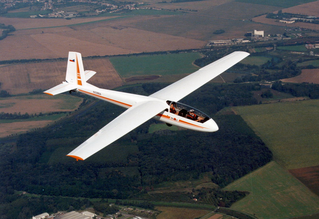
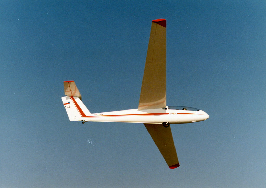
L23 Super Blaník
The world's most respected and popular two-seater training glider, the Blanik, is now available in a new improved version - the L 23 Super Blanik.
The new glider retains the the excellent flying and maintenance characteristics of the L 13 Blanik while visibility and handling are further refined.
Among many improvments are the new T-tail to minimize damage during land-outs, the swiveling tail wheel for easier ground handling and the new canopy enhancing visibility to the sides and back.
The L 23 Super Blanik is an all-metal two-seat self-supporting high-winged glider with an excellent flight characteristics and a service life of 10,000 flight hours. It has been approved for all stages of flight training from basic to advanced cross-country, aerobatic, stunt and instrument flying. It is manufactured according to the requirements of JAR 22 and is Type Certified in the USA, Canada, Brasil, Argentina, Germany, Great Britain, Spain, Austria, Sweden, Finland, Australia and other countries.
L33 Solo
The high ratings of the L 33 Solo all-metal single-seat glider are the result of sophisticated design development incorporating the latest in the soaring technology. The comfort and ease of flight and it's durability make it and obvious choice for all soaring enthusiasts. It is intended for an advance training and a performance soaring.
Pilots who received their initial dual instructions in the L 13 Blanik or L 23 Blanik will find the transition to the L 33 Solo absolutely natural.
The L 33 Solo is an all-metal single-seat cantilever mid-high wing sailplane with a semi-monocoque fuselage, fixed gear and cantilevar T-tail surfaces. It is manufactured according to the requirements of JAR 22 and is Type Certified in the Czech Republic, USA, UK, Germany, Hungary, Canada, Japan and Argentina.

RESEARCH & DEVELOPMENT
AERODYNAMICS Group
- Aircraft geometry design
- Optimization of drive unit output for specified aircraft
- Analyses of aircraft performance, stability and manoeuvrability
- Analyses of failure results
- Aerodynamic load determination (including preparation of methodologies for aerodynamic tunnel measurements)
- Certification analyses (experience in NLGS-2, FAR 23, FAR 25, CS-23, CS-25, JAR 22, JAR 23, JAR 25 standards and icing conditions)
- Preparation of methodologies for development and certification flight tests
- Incorporation of data and procedures info Flight manual
- Route and economic analyses – determination of direct operation costs (DOC)
STATIC STRENGTH Group
- Load determination and distribution over the basic structural elements
- Strength analyses of load capacity of structural units
- Strength analyses of tension distribution by means of FEM (linear and non-linear)
- Dynamic analyses by means of FEM
- Analyses of gust load by means of FEM
- Ground and flight development and certification tests
- Certification analyses (experience in NLGS-2, FAR 23, FAR 25, JAR 22, JAR 23 regulations)
FATIGUE LIFE Group
- Analyses of service of aircraft, systems and equipment used in aircraft during development, production and operation stages
- Aircraft design based on SAFE LIFE or DAMAGE TOLERANCE strategies and using FEM and FEMAP - NE/NASTRAN system
- Preparation of base documents for fatigue test execution and evaluation.
- Aircraft in operation lifetime increasing.
AEROELASTICITY Group
- Determination of aircraft design modal characteristics
- Analyses of aircraft design aeroelastic features (determination of critical velocities, flutter analyses)
- Preparation of ground and flight development and certification tests
- Certification analyses (experience in NLGS-2, FAR 23, FAR 25, JAR 23 regulations)
MASS AND CENTRE OF GRAVITY Group
- Preparation of design mass analyses
- Determination of aircraft design modal characteristics
- Analyses of admissible range for centre of gravity position
- Determination of admissible mass configurations
DESIGN Department
- Designing works concerning all systems of aircraft of Commuter, Transport and glider categories except for designing driving units
- Preparation of designing documentation in an electronic form (2D and 3D format), construction of mathematical models of surfaces and areas of aircraft and aircraft parts using AUTOCAD and CATIA software
- Elaboration of certification documents
- Preparation of drawing documentation for cooperation consisting in acceptance, decoding and transformation of base documents for production technical preparation and production
- Updating and revisions of designing documentation and instructions for service organization production (service bulletins)
DEVELOPMENT TESTING LABORATORY – AIRCRAFT TESTING
Aircraft Industries have got the Approval Certificate No. L-3-059 per § 17 of the Civil Aviation Act No. 49/1997 following Procedure CAA-TI-012-2/99 to perform compliance and verification tests of aircraft of the following categories (according to L8A Regulation ): Normal, Utility, Aerobatic, Commuter, Transport.
Aircraft Industries are authorised to perform compliance and verification tests of:
- Aircraft of the above categories and their structural parts
- Aircraft assemblies
Tests are performed according to the PART,JAR , FAR, ICAO and other Regulation bases on customer option.

АIRCRAFT MAINTENANCE
LET's dully EASA PART 145 approved maintenance organisation offers services as follows:
- Periodical maintenance P2 – R1
- Performance of modification, upgrade, modernisation in accordance with Service bulletins issued by us
- Aircraft type conversions from L 410 UVP-E to L 410 UVP-E20
- Conversion of L 410 UVP and L 410 UVP-E maintenance system from overhaul to on condition system
- Field and in-house L 410 aircraft damage repairs
- Aircraft interior modification
- Aircraft modification(s):
- Cargo kit
- Ambulance version
- First-aid version
ALUMINIUM SHEET AND PROFILE FORMING
SHEET BENDING
- Press brake (up to. = 4 000 mm, thickness max. = 3-4 mm)
- Crank presses (punching, dimpling etc.)
- Hand bending machines (bent lenghts up to = 2 000 mm, thickness max. = 2 mm)
SHEET ROLL-BENDING
- Roll-Bending Machine HAEUSLER
- Cylinder length up to = 4 400 mm, minimum radius = 22 mm, thickness max. = 3 mm
PRESSING OF FLAT SHEET – METAL PARTS USING RUBBER CUSHION
- FRICTION PRESS (parts up to = 360 x 360 x 40 mm, height up to = 40 mm)
- FLUID CELL PRESS
o parts up to 1 000 x 2 800 x 200 mm
o working pressure 25 MPa
o height up to 200 mm depending on the complexity
FORMING USING STRETCH
- Stretch forming presses
- Single or double curved formed across the block
- Height depends on stability of the block
SECTION FORMING BY STRETCHING AND ROLLING ON BLOCKS
- up to = 4 000 mm
- max. cross section. = 250 mm2
PRODUCTION OF SECTIONS FROM SHEET-METAL STRIPS THROUGH DRAWING DIE
- length up to = 6 000 mm
- sheets up to = 2 thick
PRODUCTION OF ROTARY VESSELS BY SPINNING
- max. Al sheet thickness 2 mm, max. blank diameter hand extrusion 940 mm, machine extrusion 500 mm
STEEL FORMING
STEEL SHEETS FORMING ON ECCENTRIC PRESSES
- shearing, bending, drawing, push broaching, extrusion, forging and trimming
- work table dimension from 320 x 210 mm do 1 000 x 720 mm
- ram stroke from 8 do 125 mm
- bent lenght up to = 720 mm
PRESS BRAKE FORMING
- bendign, straghtening and punching
- sheet thickness 1 to 12 mm
- work table dimensions 4 000 x 3 120 mm
- bent length up to 4 000 mm
MACHINING
TURNING OPERATION
- standard centre lathes up to 250mm in diameter and 1 250 mm in length
- automatic lathes up to 20 mm bar diameter
DRILLING AND BORING
- drilling machines (max. diameter 50mm, max distance between spindle and work table 1 345 mm)
- horizontal boring machines (work table 1 000 x 1 200 mm, height = 0 – 900 mm)
- coordinate boring machines (work table 1 000 x 1 600 mm)
GRIDING
- standard grinding machines
(centre grinding machines – external diameter up to 280 mm)
(centreless grinding machines ¤ 3 – 63 mm) )
(hole grinding machines ¤ max. 250 mm, ¤ min. 10 mm, length max. 250 mm)
- plane griding machines (part max.300 x 1 500 mm)
- cog grinding machine (module 1,5 až 6, ¤ from 30 to 315 mm, wheel width up to 100 mm)
- tool grinding machine (external ¤ up to 280 mm, centers distance 500 mm)
MILLING
- standard milling machines (parts up to 425 x 2 000 x 500 mm)
- gear milling machine
(module up to 7, wheel diameter up to 800 mm, teeth straight, helical, worm or chain)
- pantographic milling machine (220 x 440 mm. Reduction 1:10)
- single purpose milling machine for globoid and duplex globoid cogs and worms
- CNC milling machines:
| Name | CONTROL SYSTEM | BLOCK DIMENSIONS (mm) | MOVES IN AXES x,y,z (mm) | |
|---|---|---|---|---|
| V3 1600 B | Heidenhaim 410 | 8 300 x 1 600 x 600 | 6 300 x1 600 x 500 | |
| MRP-2 | UNIMERIC 723 - 3D spindle | 12 000 x 1 590 x 700 | 10 000 x 1 600 x 600 | |
| V 800 AN | Heidenhaim 530 | 2 800 x 800 x 700 | 2 440 x 800 x 580 | |
| MF 800 AN | UNIMERIC 700 CNC - 3D | 2 600 x 850 x 700 | 2 440 x 800 x 580 | |
| FUWx 315/6 | CNC- H 646 - 2,5D | 710 x 400 x 354 | 500 x 400 x 330 | |
| VF 1 TC | UNIMERIC 200 CNC - 3D | 900 x 500 x 550 | 800 x 500 x 400 | |
| FS 100 S/A3 | Heidenhaim 426 - 5 axis | 3 000 x 1 000 x 900 | 4 000 x 1 000 x 900 |
ROUTING
- TRUMATIC NC milling machines
- bundle of sheets up to 12 mm thick, (3 000) 2 500 x 1 200mm
- Milling tool min. 6 mm diameter
RAW MATERIAL CUTTING
- CORTINA S 2600 – NC oxygen cutting machine for steel sheets of 5 to 125 mm thick, working width 2 600 mm, cutting speed max. 7 m/min., cutting slot 1,6 – 4,6 mm
- circle saws (up to 40 mm in diameter)
- band saws (up to 250 mm id diameter, or 265 x 150 mm)
- table shears (width up to 2 300 mm, thickness up to 6,3 mm)
- curved shears, circular shears and vibration shears (width up to 1 000 mm, thickness 1,5 mm to 2,5 mm)
- abrasive cutting machines
SLOTTING
- with a slotting machine (up to 270 mm in height)
- cog wheel machine (module 0,7 – 3, wheel diameter up to 315 mm)
WELDING
STEEL ARC WELDING
- carbon steel, alloy steel, cast iron and cast steel, by coated (basic or special coating) electrodes, material thickness min. 1 mm
- grooving by carbon electrodes, straightening
STEEL MAG WELDING
- carbon or alloys steels, thicknesses up to 8 mm
- for maintenance purposes - surfacing
STEEL SPOT WELDING
- carbon or alloy steels, thicknesses from (0,5 + 0,5) to (3 + 3) mm
- max. thickness ratio 3:1
STEEL TIG WELDING
- carbon or alloy steels and stainless steel
- copper, thickness from 0,5 to 10 mm
STEEL OXY-ACETYLENE WELDING
- carbon, alloy or stainless steels welding and brazing, thicknesses from 0,5 to 3 mm
ALUMINIUM AND AL-ALLOY TIG WELDING
- for weldable materials, thicknesses from 0,8 to 10 mm
ALUMINIUM AND AL-ALLOY OXY-ACETYLENE WELDING
- for welding and brazing thicknesses from 0,6 to 5 mm
- washing in baths 2 800 x 680 x 1 230 mm
ALUMINIUM AND AL-ALLOY SPOT WELDING
- for aircraft parts from (0,6 mm + 0,6 mm) to (2,0 + 2,0 mm), max. thickness ratio 3:1
- tests are necessary for thicker materials
RIVERTING
MANUAL RIVERTING
- manual riveting for rivets up to 5 mm in diameter (Al-Alloy)
MACHINE RIVERTING
- machine riveting on hydraulic and pneumatic presses for parts up to 1 500 x 6 000 mm
RADIAL RIVERTING
- BRACKER radial riveter
- Al-Alloys rivets up to ¤ 5 mm (solid rivets) or ¤ 10 mm (tubular rivets)
ONE-SIDED RIVERTING
- manual
- pneumatic, rivets up to ¤ 5
- Special fasteners pneumatic installation (Lockbolt GP a LGP ¤ 4 mm a ¤ 5 mm)
SURFACE TREATMENT OF ALUMINIUM
Computer-controlled automated line with recording and archiving data for processes:
YELLOW CHROMATING ALUMIGOL B
- This coating provides corrosion resistance of parts combined with excellent adhesion. Thus treated surface is suitable for coating systems or application of powder coating.
- Usable internal dimensions of the bath: length 5500 x width 1900 x depth 600 mm.
COLORLESS CHROMATING ALODINE 1500
- The surface treatment provides corrosion protection of aluminum and is an excellent binder for transparent organic surfaces. It is used when the characteristic appearance of aluminum is needed.
- Usable internal dimensions of the tank: length 1800 x depth 800 x width 700 mm
ENVIROMENTAL TESTING OF CORROSION RESISTANCE
Salt spray chamber
HARDENING SHOP
Newly refurbished hardening shop, equipped with computer for monitoring, recording and archiving of data:
HEAT TREATMENT OF ALUMINIUM
- salt bath for heating and cooling (solution annealing) of sheet metal parts such as aircraft structures
- processed materials Z424203, Z424253, AA 2024, ALCLAD 2024, DIN 3.1354, 3.1364
- max. size of parts: 5800 x 2000x 500 mm
HEAT TREATEMENT OF STEEL
- annealling, normalizing, hardening, cementation of the surface
- carbon steel,alloyed up to class.16 (according to ČSN)
- max. size of parts: 1200x600x450mm
PAINTING
- Painting with use of polyurethane, epoxy, acrylic, nitrocelulose and synthetic coatings.
- Painting Boxes 6 x 4 m, 20 x 7m. Painting Hall 60 x 32 meters.
- Experience with painting interior parts for aircraf, buses, train units, etc.
Aircraft Industries a.s.
- Na Zahonech 1177, 686 04, Kunovice, Czechia
- +420 572 816 004
- +420 572 816 006
- let@let.cz
- www.let.cz
